 |
 |
|
Kurzbeschreibung:
Dekatrons sind Zählröhren welche mit Glimmentladungen
arbeiten (wie Glimmlampen und Stabilisatoren). Meist haben sie 10 Zählzustände
(Dekade). Durch anlegen von Pulsen an ein oder mehrere Steuerelektroden
(guides) schaltet das Dekatron zur nächsten Zählposition weiter. Die Position
ist meist durch Glimmen ersichtlich. An den Stiften sind entweder die Kathoden
aller Zählpositionen einzeln herausgeführt oder zu Gruppen zusammengefasst
(z.B. Kathoden 1-9 und 0).
Indem man den Strom der Kathoden beobachtet kann man
die jeweilige Position feststellen und so z.B. bei Position 0 auch einen
Übertrag an die nächste Zählröhre einleiten.
Details siehe gängige Literatur.
|
Short Description:
Dekatrons are gas filled counting tubes that work with glow discharge
(like glow lamps and voltage
stabilizer tubes). In most cases they have 10 counting positions (a
decade). By applying pulses
to one or more control grids (guides) the Dekatron switches to the next
counting position. The
counting position is normally shown by a glowing element. The pins are
either connected individually to the cathodes of all counting positions or to
groups of them (e.g. cathodes 1-9 and 0). By monitoring the current at the
cathodes the current counter position can be determined. This allows generating
a carry signal to the next counter tube e.g. from counter position 0.
For the details please see the respective literature.
|
|
Typen:
Die überwiegende Anzahl der Dekatrons hat 2
Steuerelektroden (guides). Es gibt aber auch welche mit 3 oder nur einem. Durch
anlegen einer bestimmten Signalfolge an die Guides wird die Zählposition
weitergeschaltet.
Es wurden von vielen Herstellern unterschiedlichste
Typen, mit leider nicht kompatiblen Daten und Anschlussbelegungen, hergestellt.
Ich habe eine unvollständige Tabelle gängiger Typen
angelegt und dabei die Dekatrons möglichst nach gleichen/ähnlichen
Sockelschaltungen sortiert.
|
Types of Dekatrons:
The vast majority of Dekatrons has 2 control grids (guides). But there are also some with 3 control
grids or just one control grid. Applying signals in a certain order to the control grids (guides) switches
the tube to the next counting position.
Many manufacturers have built tubes of very different types.
Unfortunately the data and the pin assignments are incompatible in most
cases.
I created an incomplete table of some common Dekatron types and tried to sort it according to same/similar pin assignments. |
Dekatrons.xls
|
|
Anschlüsse:
Anode: Wird über Strombegrenzungswiderstand an eine
positive Anodenspannung gelegt
Guides: Steuerelektroden. Im Ruhezustand positiv. Im
Schaltzustand negative Signalfolge.
Kathoden: An Masse zu legen (evtl. über Widerstand
um einen Stromfluss zu detektieren).
|
Electrical connections:
Anode/Plate: Connect to a positive anode supply with a current limiting resistor in series.
Guides: Control grids. At a positive level in idle state. Negative signal sequence when switching.
Cathodes: Connect to ground (perhaps with series resistor(s) to monitor current flow). |
|
Prüfung von Dekatrons mit dem RoeTest
Die Prüfung der Dekatrons benötigt nur eine sehr
geringe zusätzliche Beschaltung, welche in eine spezielle Fassungsbox eingebaut
wird. Spannungen und Steuersignale erzeugt das RoeTest.
|
Testing Dekatrons with the RoeTest:
Testing Dekatrons with the RoeTest requires only very little additional
circuitry that can be mounted into a specific socket box. The RoeTest
supplies the voltages and the switching control signals. |
|
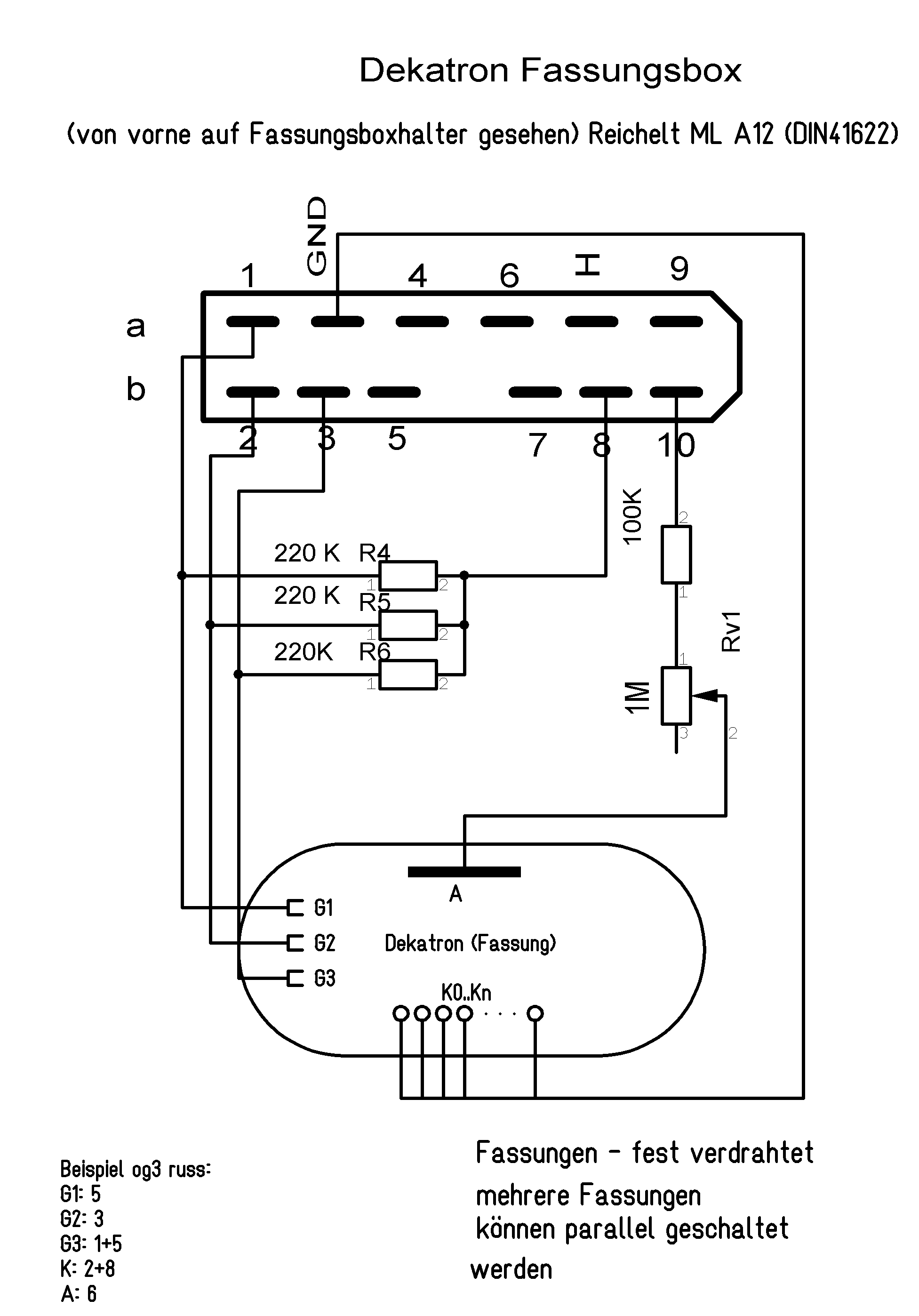
Die grundsätzliche Schaltung:
Leider können die Stifte der Dekatrons nicht
automatisch zugeschaltet werden. Die Fassungen sind also für die
unterschiedlichen Dekatrons fest zu verdrahten. Nach meiner Tabellen können
immerhin verschiedene Dekatrons zu
Gruppen zusammen gefasst(kompatible Sockelschaltung), und in derselben Fassung
geprüft werden. Abweichend von meiner Empfehlung für normale Vakuumröhren
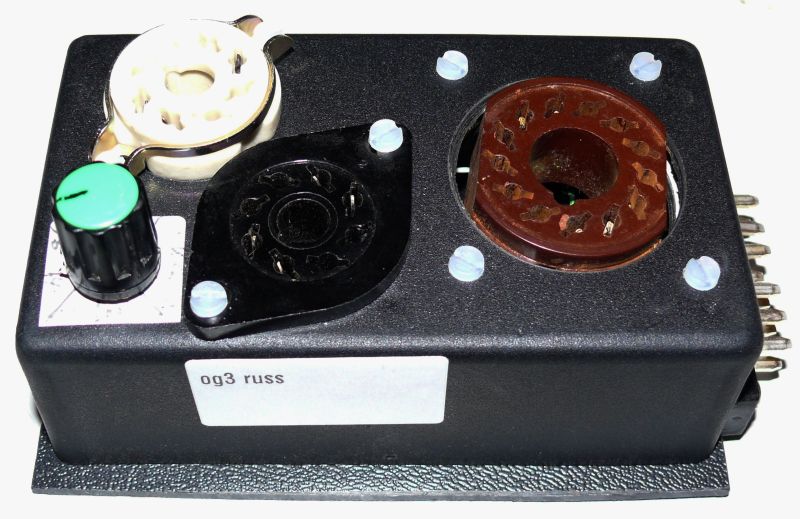
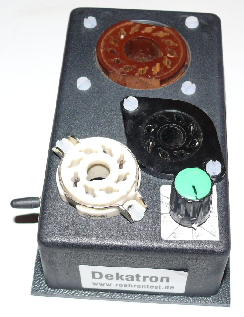
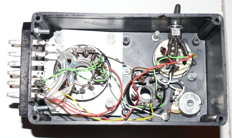
können bei Dekatrons beliebig viele Fassungen in eine Box eingebaut werden. Ich
habe mir z.B. eine Box für die gängigen Russischen Dekatrons gebaut:
|
Basic circuitry:
Unfortunately the Dekatrons' pins cannot be switched automatically. So
the sockets for the different Dekatron types must be hard-wired.
According to my table it is at least possible to combine different
Dekatrons (with compatible pin assignments) into groups and test them
in the same socket. However, in contrast to my recommendation for
vacuum tubes, you may
mount as many sockets for Dekatrons as you want into a single socket
box. For example I built a single socket box for the common Russian
Dekatrons: |
 |
 |
 |
 |
 |
|
eine Fassung für A101, A102, A103
eine Fassung für og3
eine Fassung für og4, og7, og9 und mit Umschalter
für og8
|
one socket for A101, A102, A103
one socket for og3
one socket for og4, og7, og9 and with a switch for the og8 |
|
Prüfung/Software:
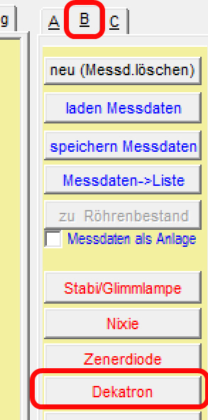
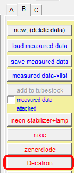
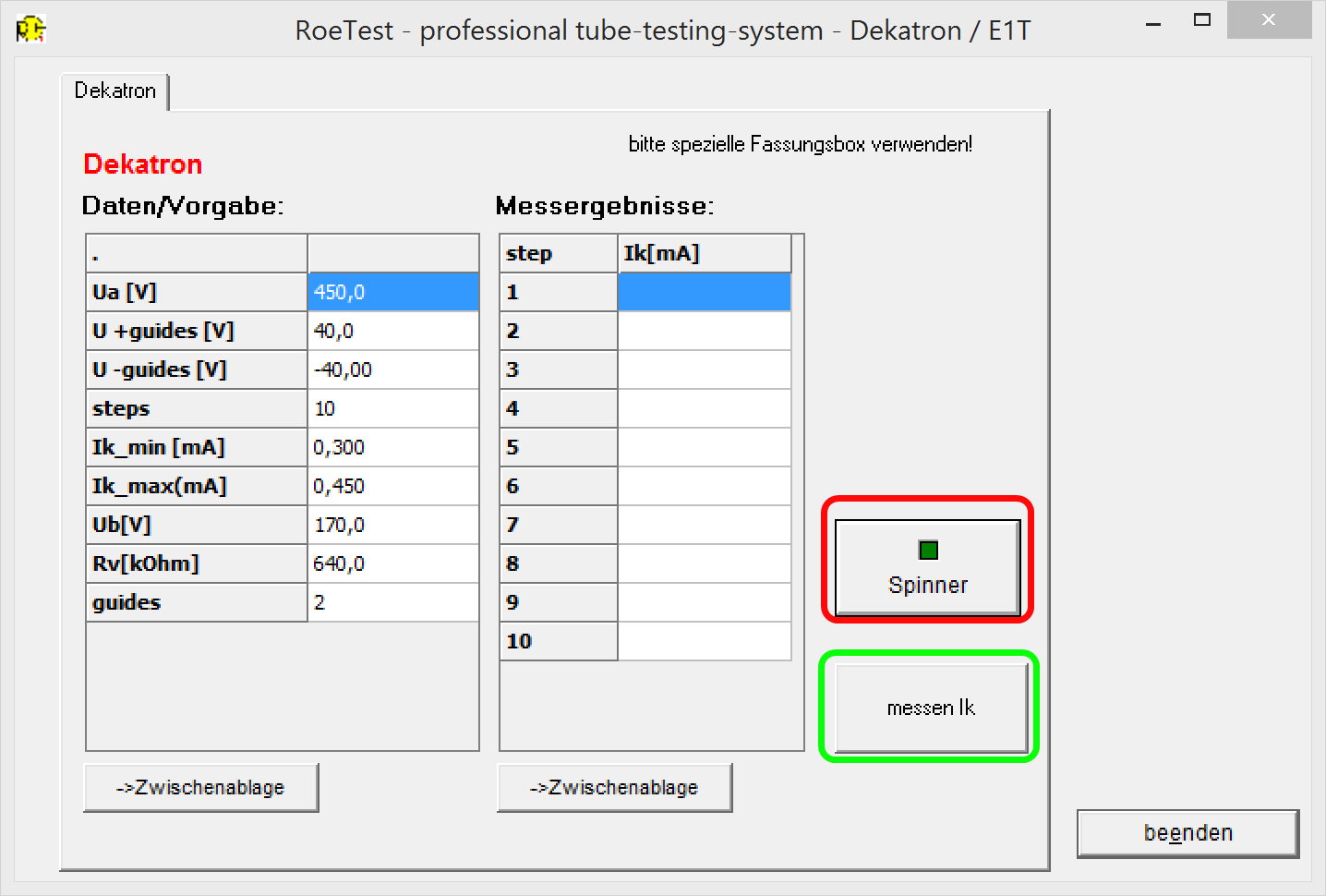
Ab Software V 10.3.1.0 gibt es für die Röhrenart
"Dekatron" einen eigenen Modus:
|
Testing/Software:
Starting with Software V 10.3.1.0 there is now an own mode for the tube type "Dekatron": |
|
|
 |
|
Prüffunktionen:
1. Spinner
Damit kann man den Schaltzustand laufend
weiterschalten und anhand des Glimmens die Position verfolgen.
|
Test functions:
1. Spinner
Continuously switch the counting position and watch the change of the glow position. |

Video Spinner |
|
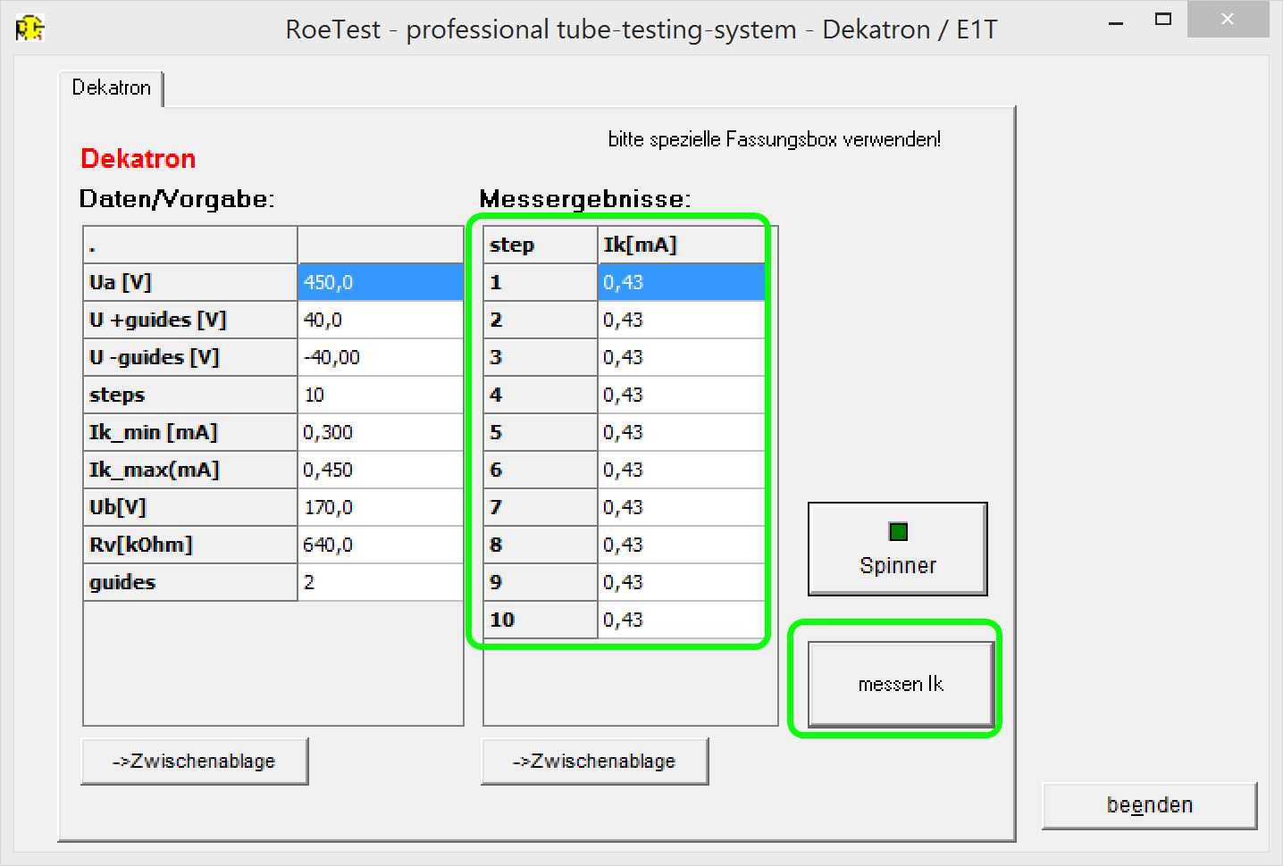
2. messen Ik
Messen der Kathodenströme der jeweiligen
Schaltpositionen (Kathoden). Die Ströme durch die Kathoden sollte in etwa
gleich sein. Keine Aussage hat die absolute Höhe des Stroms, da dieser durch
den Vorwiderstand bestimmt wird.
|
2. measuring Ik (“messen Ik”)
Measurement of the cathode current of the respective switch position
(cathode). The cathode currents of all the cathodes should be
approximately the same. The absolute value of the cathode current is
irrelevant as the currents are determined by the cathode resistor (in
the socket box).
|
 |
|
Für beide Tests zu beachten:
In
der Fassungsbox befindet sich ein Vorwiderstand (Festwiderstand in Reihe mit
einem Potentiometer). Das Potentiometer versieht man mit einer
Widerstandsskala. Vor Starten einer Prüfung stellt man das Potentiometer grob
auf den richtigen Widerstand (Rv) ein. Nach starten der Messung ist der Strom
mit dem Potentiometer auf den richtigen Wert (zwischen Ik_min und Ik_max)
einzuregeln. Bei zu geringem Strom kann das Dekatron nicht weiterschalten. Bei
zu hohem Strom kann das Dekatron beschädigt werden.
|
Note for both tests:
There is a series resistor (a fixed resistor in series with a linear
potentiometer) built into the socket box. Make a resistance scale and
apply it to the potentiometer for easy adjustment. Before starting a
measurement set the potentiometer's resistance coarse to the required
resistance value (Rv) for the tube. After starting the measurement adjust the cathode current
with the potentiometer to achieve the correct value (between Ik_min and
Ik_max). If the current is too low the Dekatron cannot change its
counting position but a too high current might damage the Dekatron. |
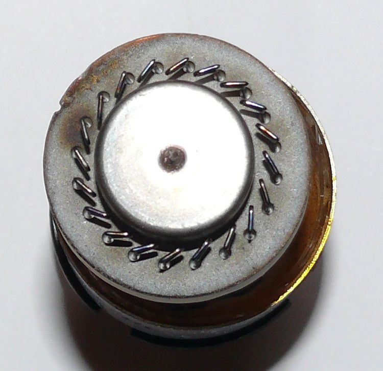
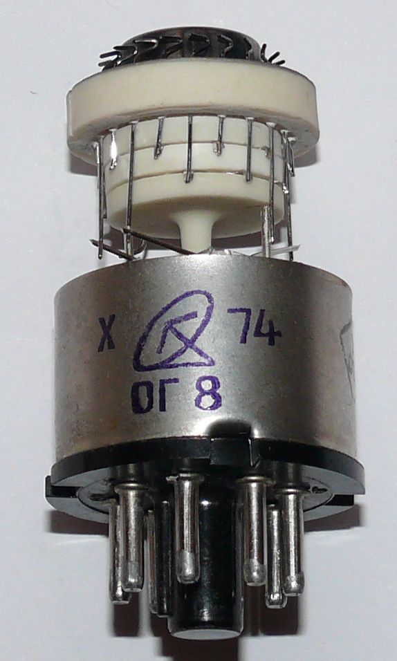
| Hier
noch Bilder eines defekten Dekatrons (leider beim Versand zu Bruch gegangen).
Das runde Blech in der Mitte ist die Anode. Rundherum sind die 10 Kathoden und
Steuerelektroden (guides) angeordnet. Bei Betrachtung des Aufbaues kann man
sich gut vorstellen, wie die Glimmentladung durch das Anlegen der Impulsfolgen
von Kathode zu Kathode gezogen wird. |
In
the following some pictures of a broken Dekatron (was unfortunately
destroyed during shipment). The round sheet metal in the middle is the
anode/plate. All around are the 10 cathodes and the control grids
(guides). Looking at the structure you can easily imagine how the glow
discharge is guided from cathode to cathode by applying the switching
signals' sequence.
|
  |
 RoeTest (Röhrentest)
 RoeTest (Röhrentest)


