menu
| RoeTest von Martin Forsberg V9
Martin sends me some pictures from his RoeTest V9
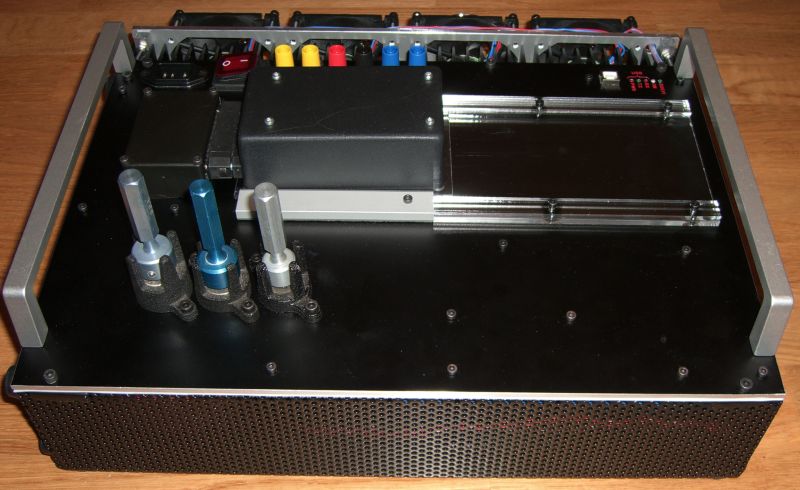
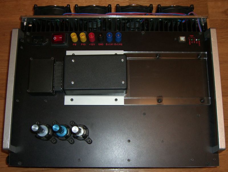
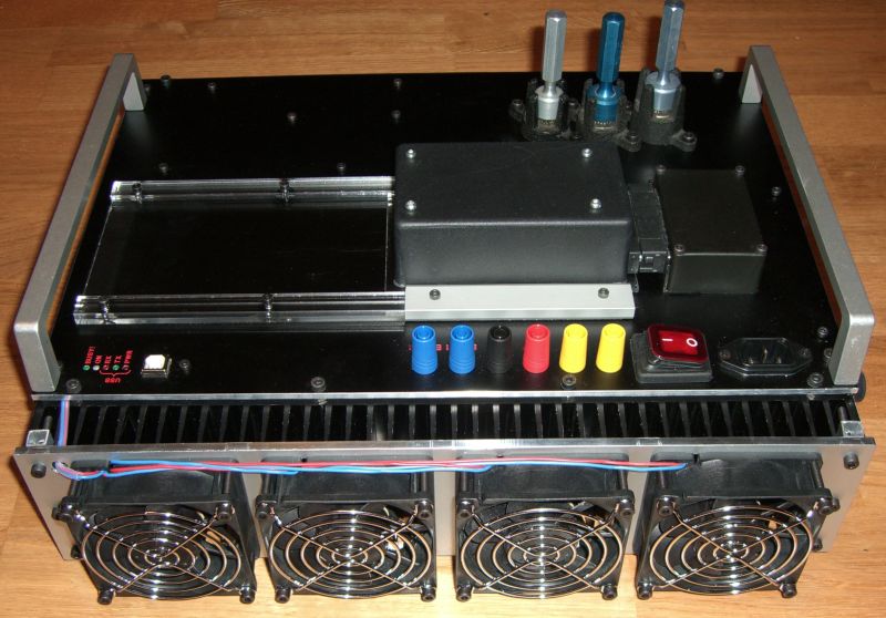
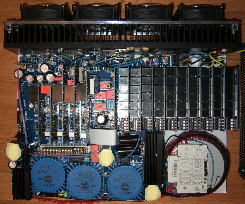
He sends me this email:
Dear Helmut,
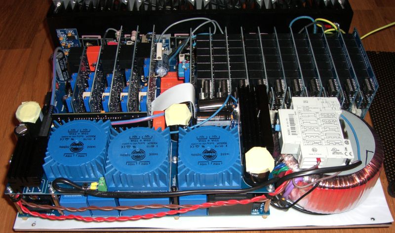
I've finally finished the build of my
Roetest V9 and it is calibrated good enough for me (I can't tweak the
calibrations any more).
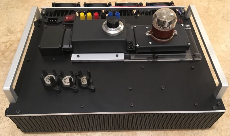
I've included a few
photos of the outside and inside. The difference from your design on the
outside is the two handlebars on each side (they let me turn it upside
down without the banana plugs touching the table), the three tube pin
straighteners and tube socket straighteners (the three handles with
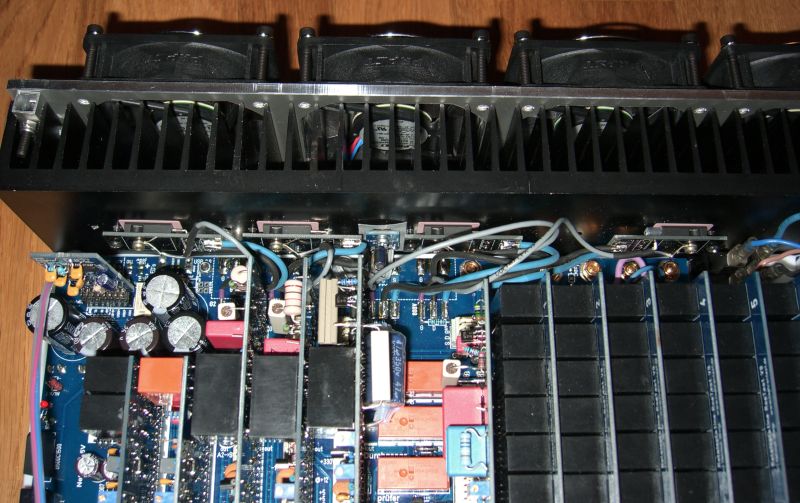
pins) and lastly the four fans mounted on an aluminium plate that is
attached to the heat sink and controlled by the extra power supply that I
put inside!
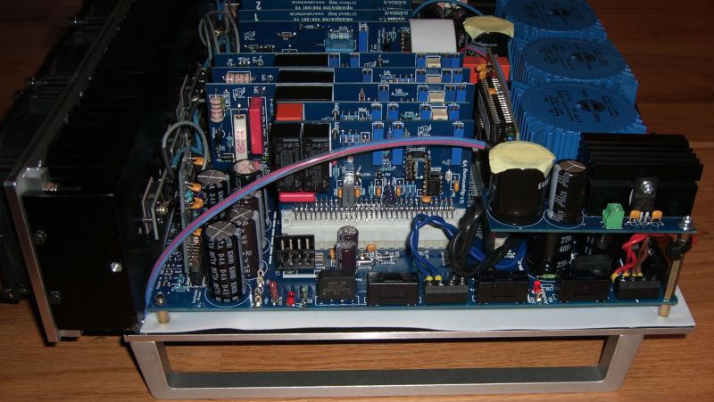
On the insides I have moved the
mosfets so that they are connected by wires and they are also spread out
more evenly on the heatsink to distribute the heat some more. I've
included the power on timer on top of the power transformer and there is
a large circuit board with three toroidal transformers, one for the
fans and two in parallel for the +12V output connector - beneath this
PCB I have also included one extra relay that switches the power to all
of the output relay cards.
I made the hole
above the front mounted rectifier bridge larger, approx 1cm wide, so
that I could more easily access it if I need to remove the circuit
board.
Making the extra circuit board on top
for the extra 12V output and extra fan power took some time as it wasn't
easy to cram all transformers and components on top and at the same
time have access to the mounting posts so that I could screw it down
securely, but in the end I succeeded on the first try with the PCB. It
works very nice and only has linear regulators, LT1085/86CT types.
Now I get enough power to my external adapters without an external power supply.
Kind regards,
Martin
22.11.2017:
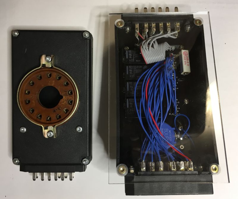
Martin sends me additional pictures of his Nixie tester adapter:
Here
are some photos of the Nixie adapter that I built after to your
drawings, I made a small PCB that I screwed to the top which holds the
relays and a 1 kOhm resistor plus a 50 kOhm/3W 10-turn potentiometer.
The potentiometer has a counting knob so that I know that for each turn
it adds 5 kOhm, 10 turns and you have a maximum of 51 kOhm whereas the
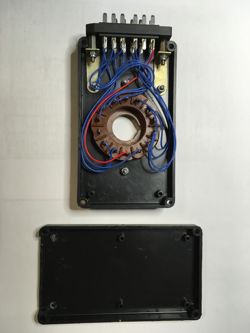
minimum is 1 kOhm from the resistor. I used two DIN 41622 female
connectors to get all 17 pins plus the anode out on the other side of
the box, there I can connect a second adapter for the Nixie socket/s.
I also finally found a use for the lids from the boxes used for the
ordinary socket adapters, they make up a very thin socket adapter which
I will use for Nixie-sockets just like the one in the photos.
Kind regards,
Martin
|
|
 RoeTest (Röhrentest)
 RoeTest (Röhrentest)


