menu
|
Mixing tubes
Measurement of anode current and slope of a mixing tube, with the operating parameters from the data sheet (externally added HF alternating current) with the RoeTest
(Display of the HF current with external additional instrument)
according to Michael Niermann
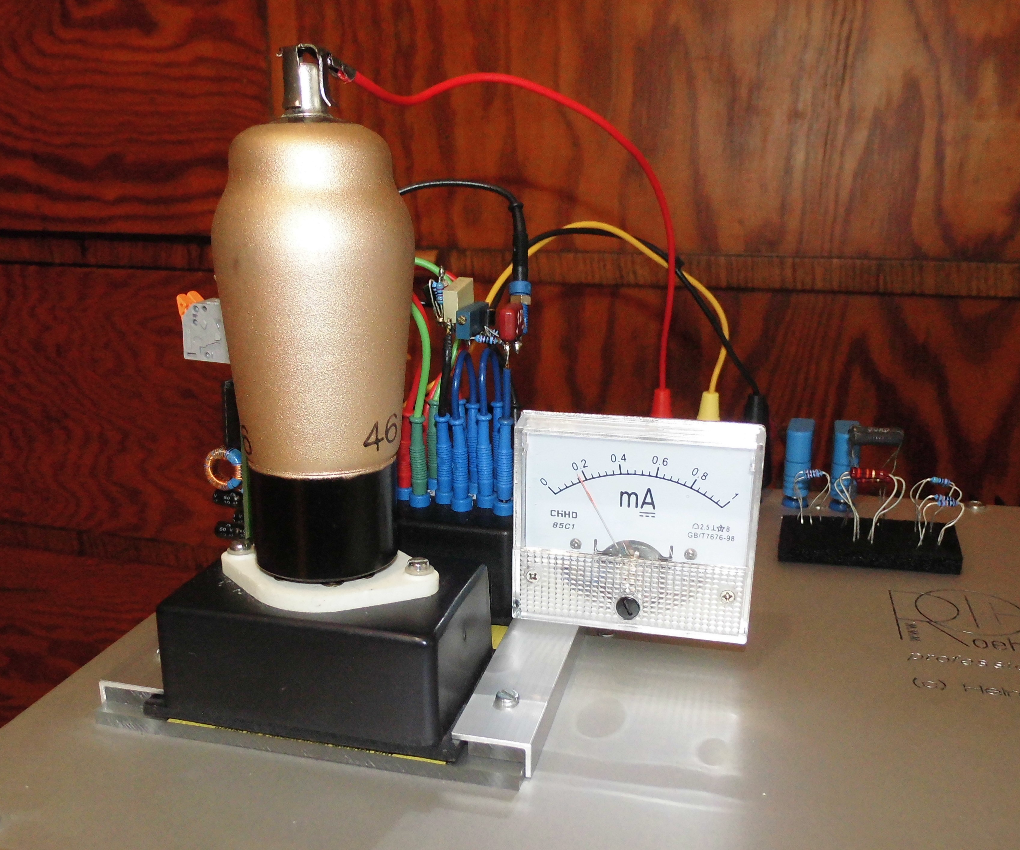
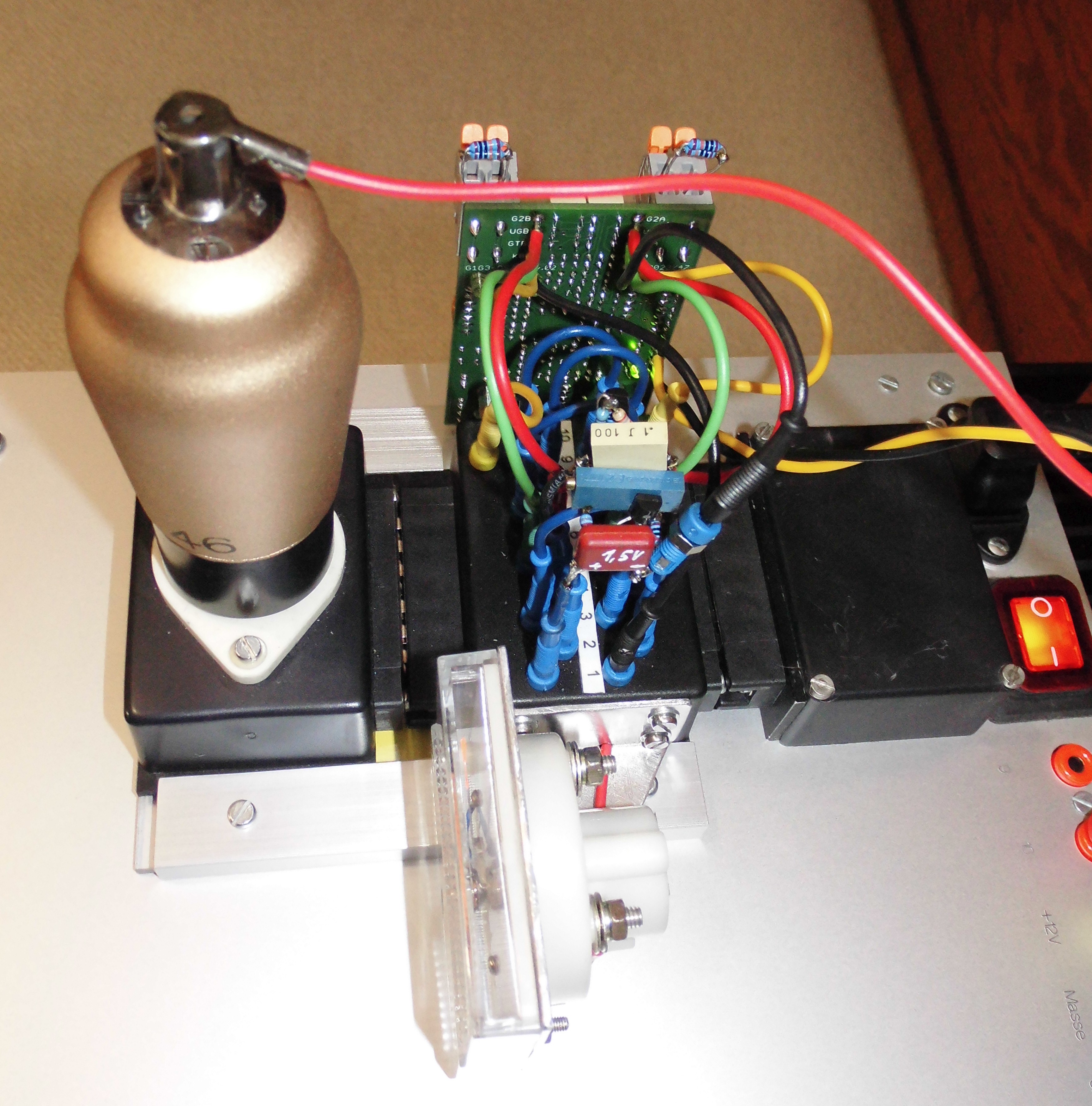
Test setup with the AK1: The shunt regulators can be seen in the
pictures. With the first one, the +90V voltage from the RoeTest is
reduced by 20V, i.e. to 70V, and fed to the G3 (pin 5). The second
shunt regulator generates a voltage of 1.5V, which lies in the cathode
line (pin 1).
Advance notice from me:
This is a very special measurement that not everyone needs. Anyone who
dares to do this should know exactly what they are doing, as there is a
lot that can be done wrong. Simply plugging it in incorrectly could
lead to defects. You should also be able to use an oscilloscope,
otherwise you will not be able to set the oscillator's limiter circuit.
I would like to point out the dangers of high voltages again. This is
particularly true for open, experimental, touchable circuits. Replicas
are without my liability and without the liability of Michael Niermann.
All rights to the idea, the circuit and the documents belong to Michael
Niermann.
Note: The circuit may emit RF. This is an experimental setup. There is
no guarantee as to whether operation is permitted. Replica builders are
responsible for not causing any interference through HF radiation.
Shielding is recommended.
If anyone wants to reproduce the experiment and recreate the circuit,
they will have to do it themselves, as neither Michael nor I have time
for support, and also get special parts themselves (such as OPA4227,
J310 transistor, LT1227, AZ431L) . If anyone is interested in a circuit
board, please feel free to contact me (there are only a few pieces
available).
For
measuring mixing tubes in operating condition, i.e. with HF, Michael
Niermann has a great idea and implemented it with a lot of work. He
explains exactly what it's about in this PDF description:
MR G1G3-OSZ_02_description_04_EN.pdf
During
the measurement, HF current flows in the lower medium wave range (for
me around 530 kHz), the level of which is approximately on the same
scale as the actual operation of the tube in a radio.
Die Schaltung:
MR circuit diagram 15.03.2024.pdf
Note on the circuit diagram:
The additional device is looped in between the RoeTest and the socket box (tube).To do this, supply lines are interrupted (e.g. socket pair with short-circuit plug).The sockets on the additional circuit board "xxA" face the RoeTest and the sockets "xxB" face theTube.
Assembly plans:
MR G1G3-OSZ_02b_assembling_01.pdf
MR G1G3-OSZ_02b_assembling_02.pdf
Component parts list:
MR G1G3-OSZ_02_bill of materials_02 03/15/2024.pdf
Addendum:
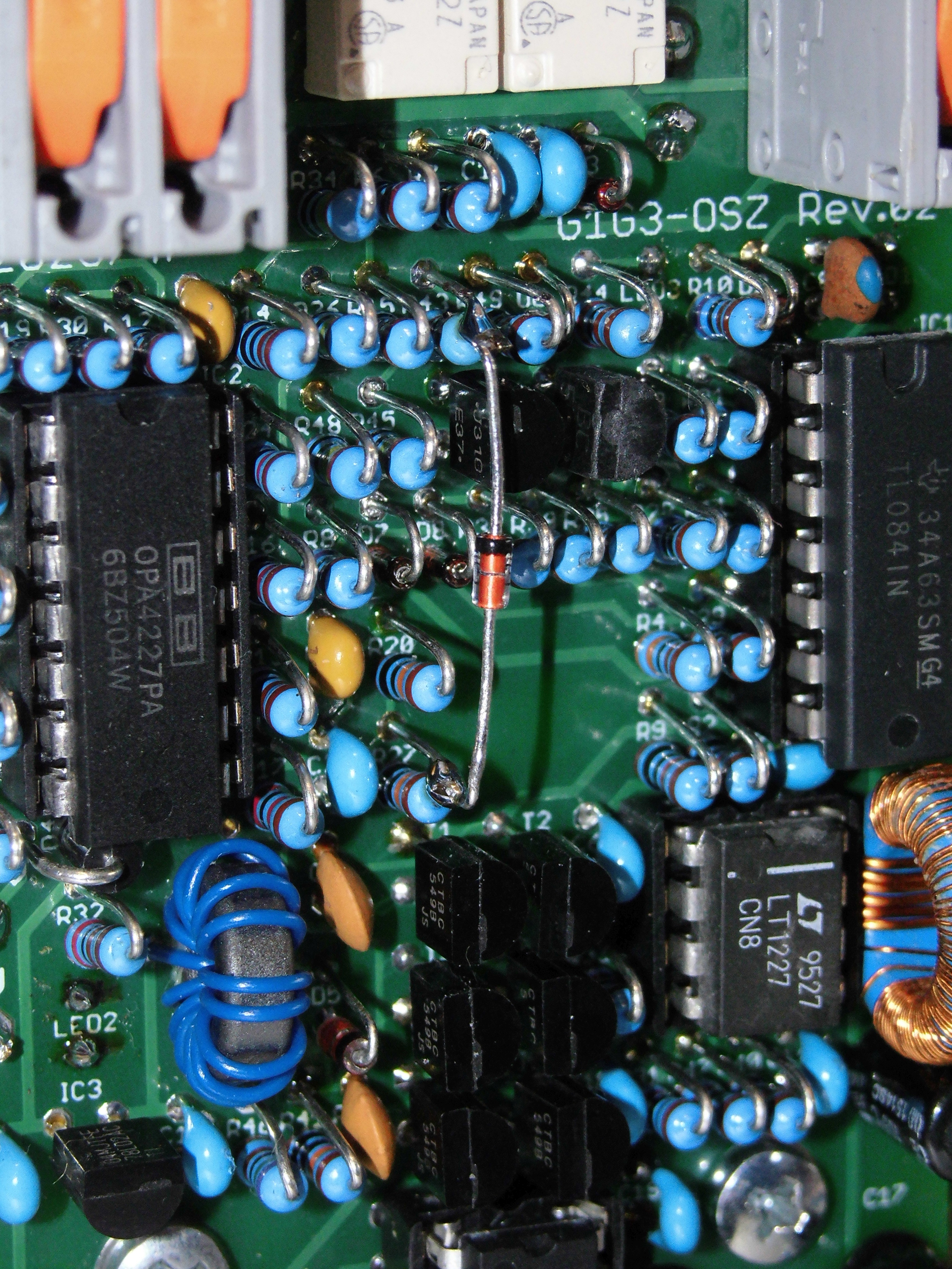
The
diode D9 was subsequently added so that the oscillator is only
activated during a measurement. The diode should be soldered in as
follows:
Michael has created a worksheet with a calculation formula (OpenOffice) for the shunt controller with the AZ412L:
MR AZ431L_Formel_02.ods
Michael has put together an extensive table for the mixing tubes (Libre Office):
MR mixing tubes_table_04.ods
Example information in data sheets for mixing tubes and their interpretation:
ECH42.pdf
ECH81.pdf
AK1.pdf full data sheet: https://frank.pocnet.net/sheets/204/a/AK1.pdf
Special data in the RoeTest database:
For some mixing tubes he has created special data in the RoeTest database for measurements with his additional device.These
special tube data all have the additional designation "...
ext.HF->g1, Ig=xxxµA" or "...ext.HF->gt+g3,
Ig=xxxµA". If you load this data into the measurement
software, it will be displayed (green) which cable colors of the
additional device should be connected to which sockets (insert box -
distance from short-circuit plug). The additional device has cable
connections for the side facing the RoeTest (input) and the tube
(output). There is only no need to pull out a short-circuit plug for
the shield grid connection, as only one connecting cable is required
here (red).

now my attempts:
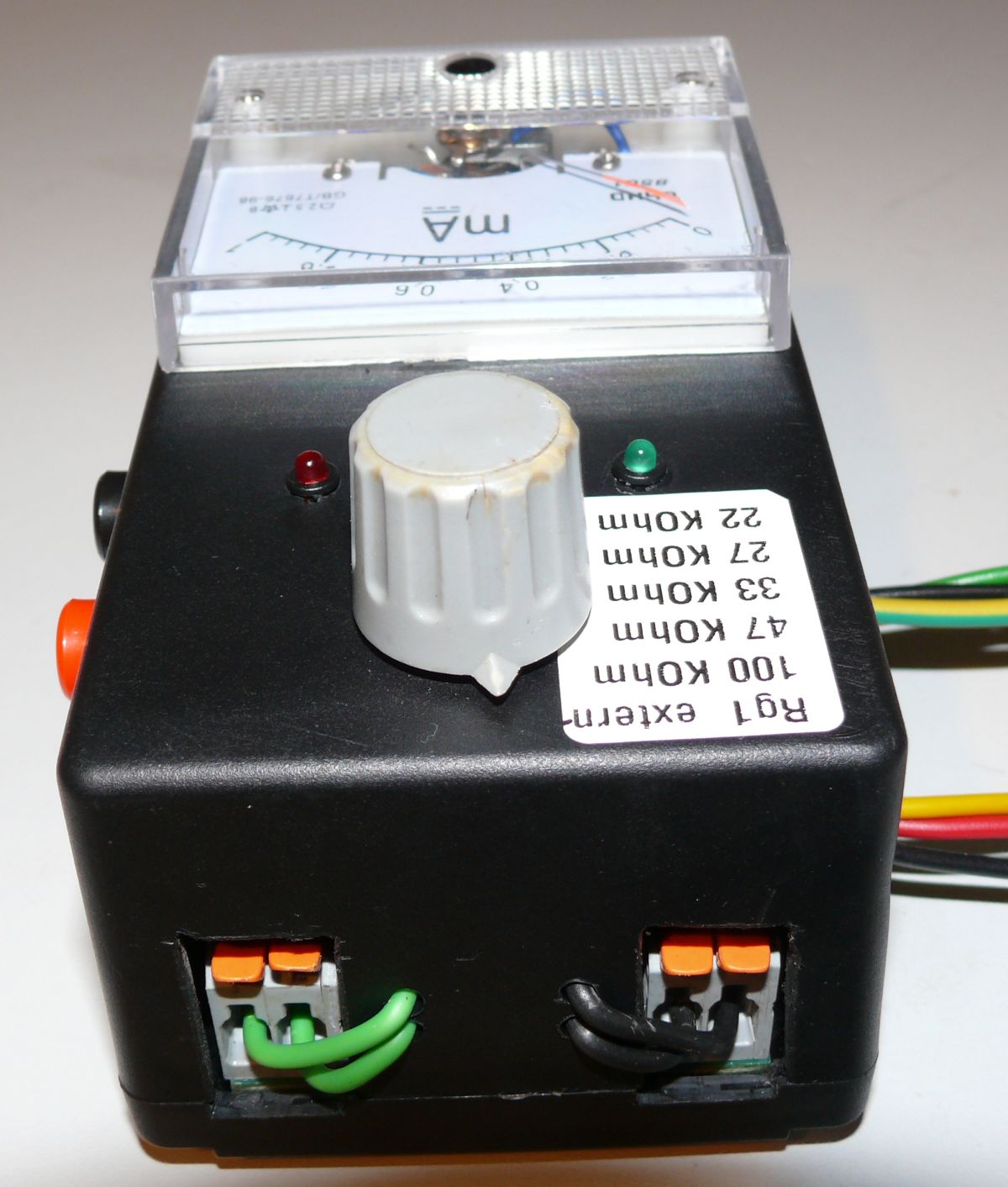
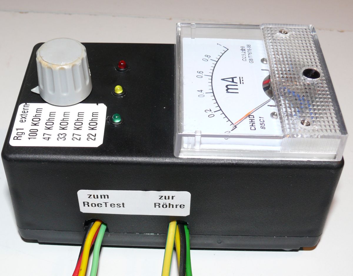
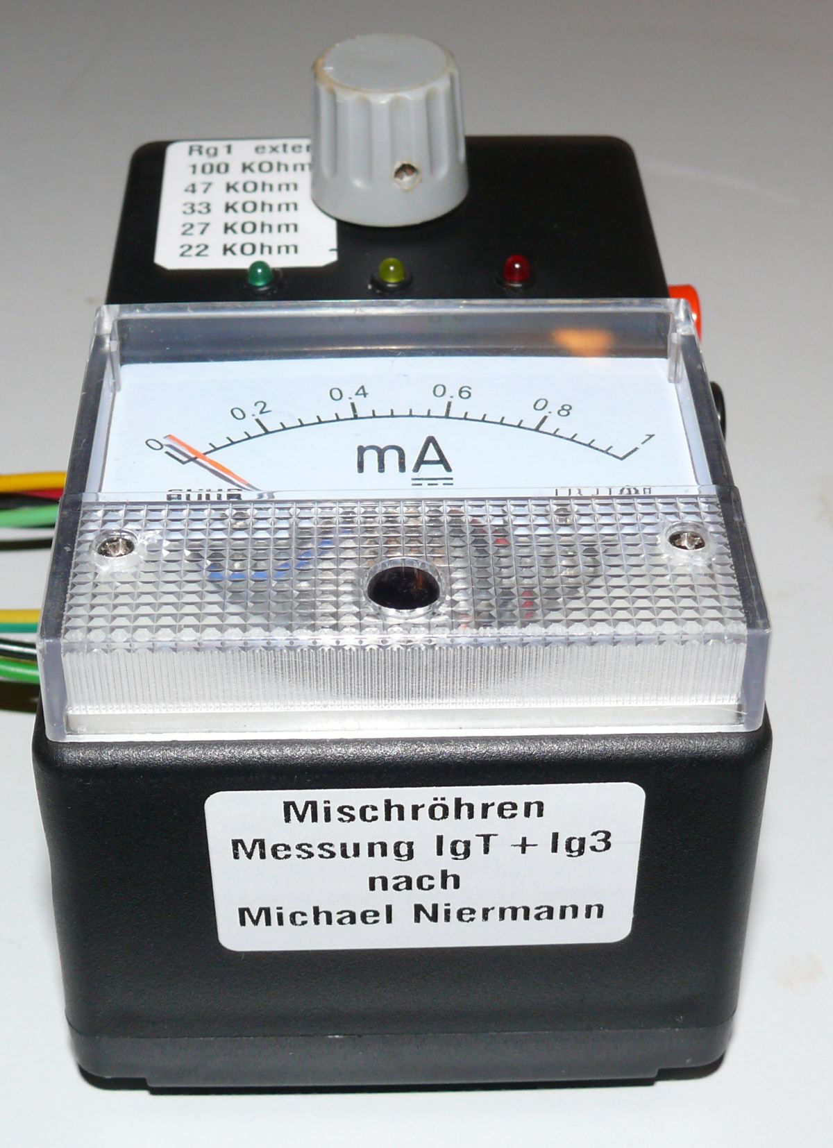
Michael was kind enough to give me a fully assembled circuit board along with a measuring instrument.I just had to put everything together.
Since I already have an insert box, I only needed to install the circuit board and measuring instrument in a housing.The
device is powered by an external 12V laboratory power supply
(unearthed). The negative socket must be connected to the ground socket
of the RoeTest. It
is intended that the two resistors (Rg1) are connected to the circuit
board. Since I installed the circuit board in the housing, it's a bit fiddly. I therefore installed a step switch (2 x 6 positions) with which I can change the 5 most important ones
switch resistor pairs (22, 27, 33, 47 and 100 KOhm). The sixth
switching position is unoccupied. If the internal resistors don't fit, can be done in the sixth switching position by connecting external resistors.

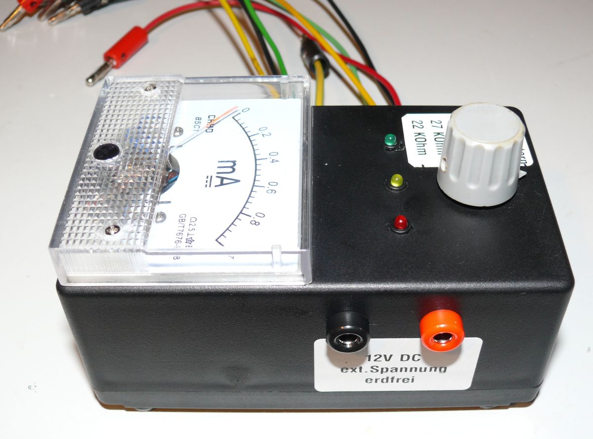
Test setup AK1:
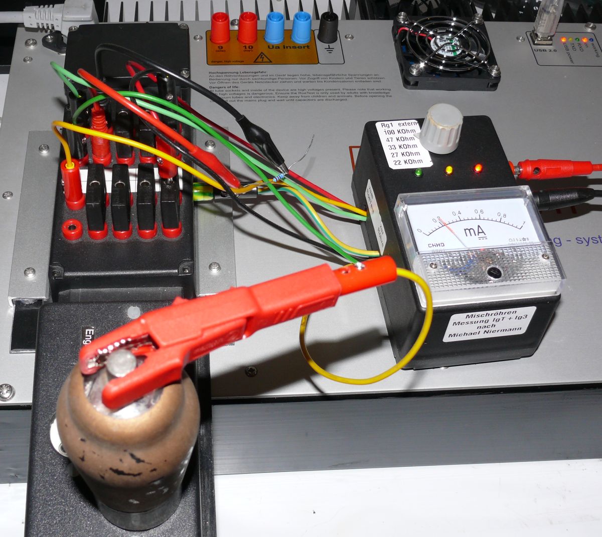
As soon as
the tube becomes warm, the RF current also flows, which is indicated by
the external instrument. Then the green LED also lights up.
Test setup ECH81:
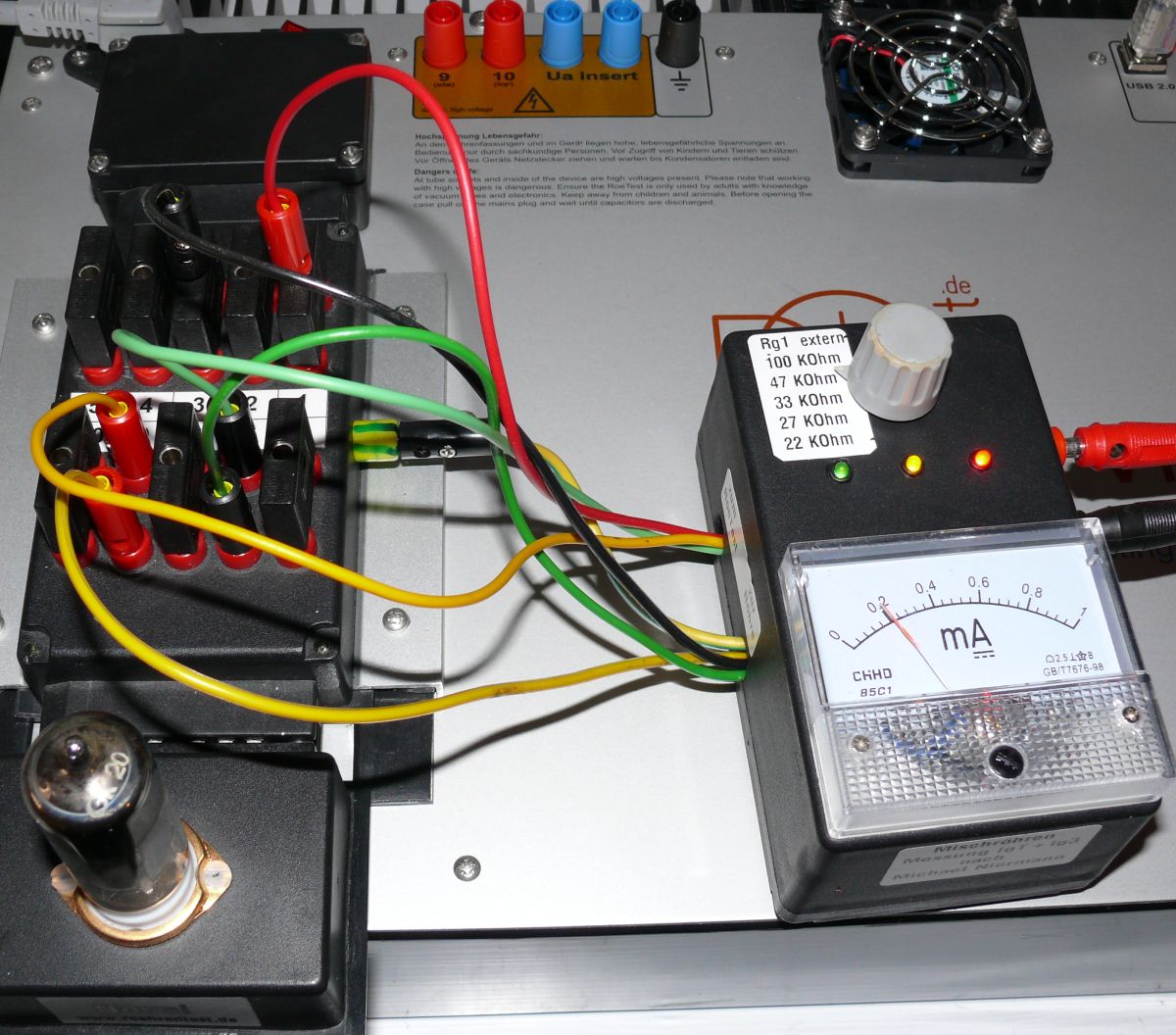
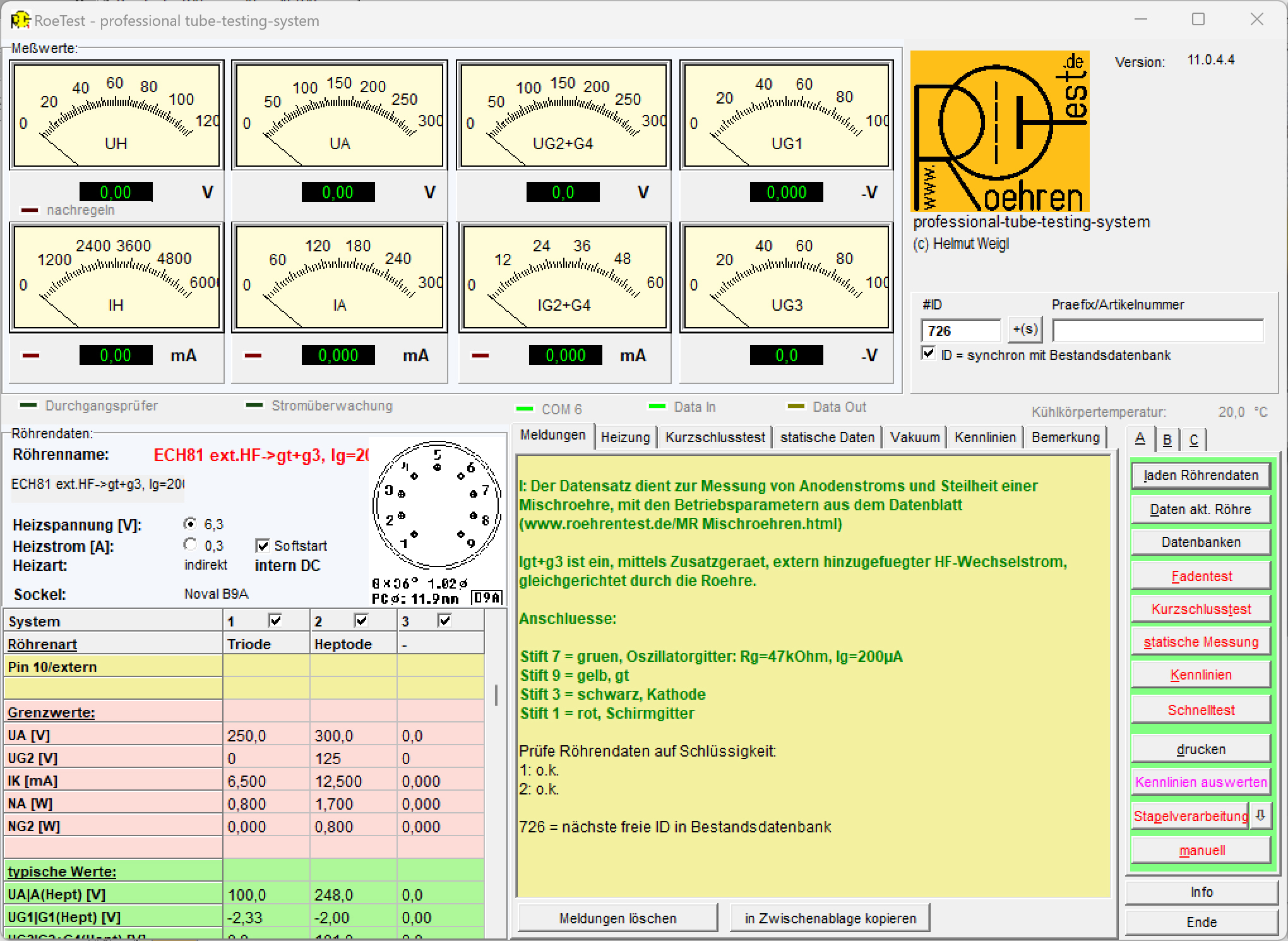
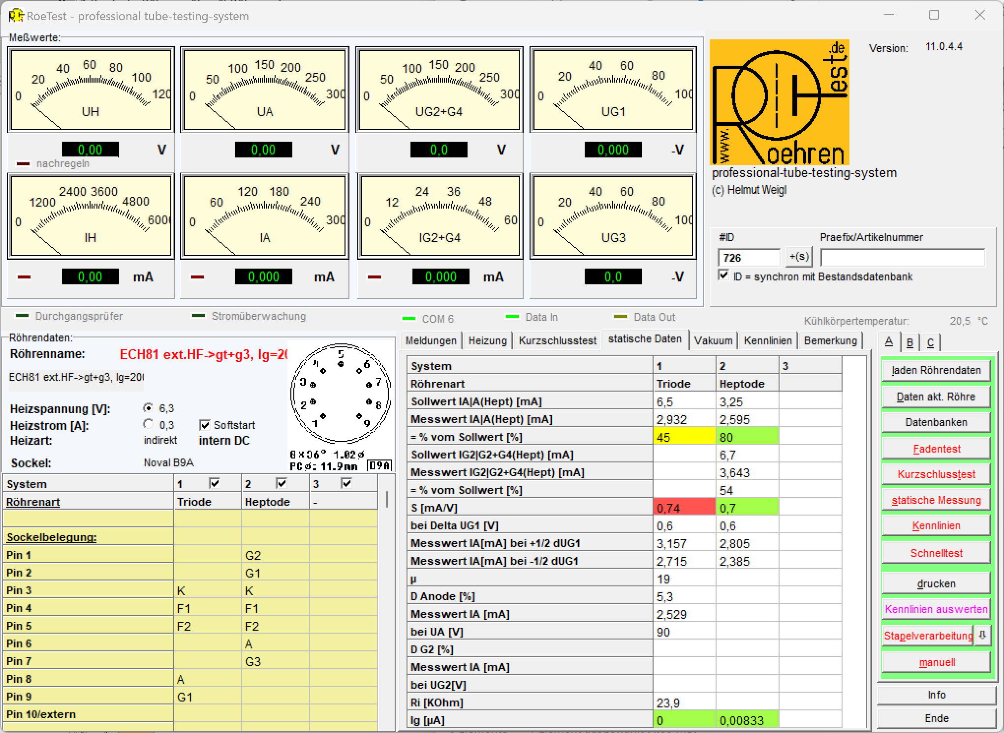
The triode is measured normally. The external circuit with the HF current only switches on at the heptode.
Dear
Michael, I would like to thank you for your extensive work, for the
good cooperation and for the printed circuit board as a gift.
|
|
 RoeTest (Röhrentest)
 RoeTest (Röhrentest)


